The car
This is a post about a car, and how I made a 60fps instrument cluster from scratch in C++. You will be subjected to unprofessional videos and some novice-tier graphics.
If that sounds boring, it'll be boring. You can still leave this page if you want!
I have a 1987 Toyota MR2.
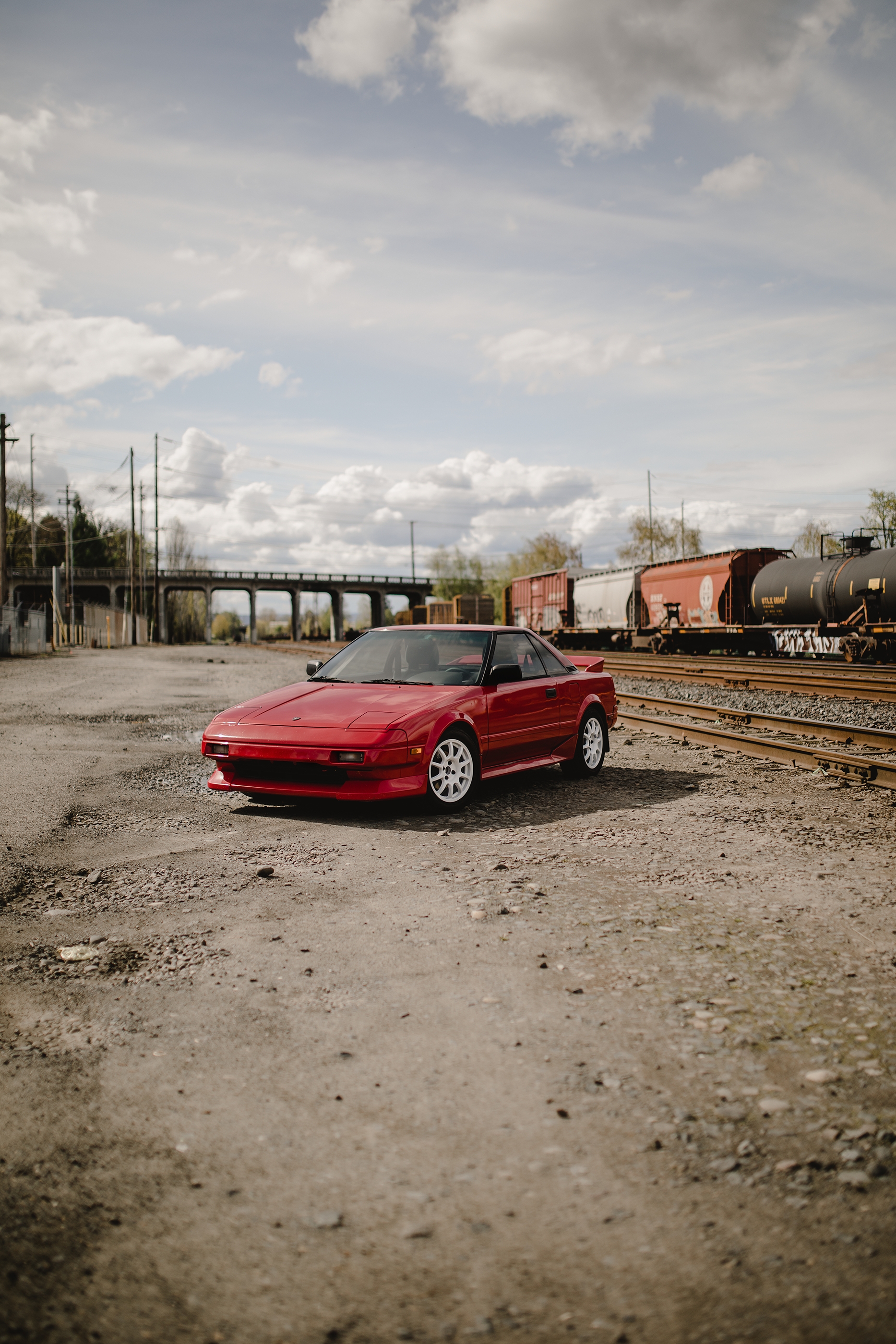
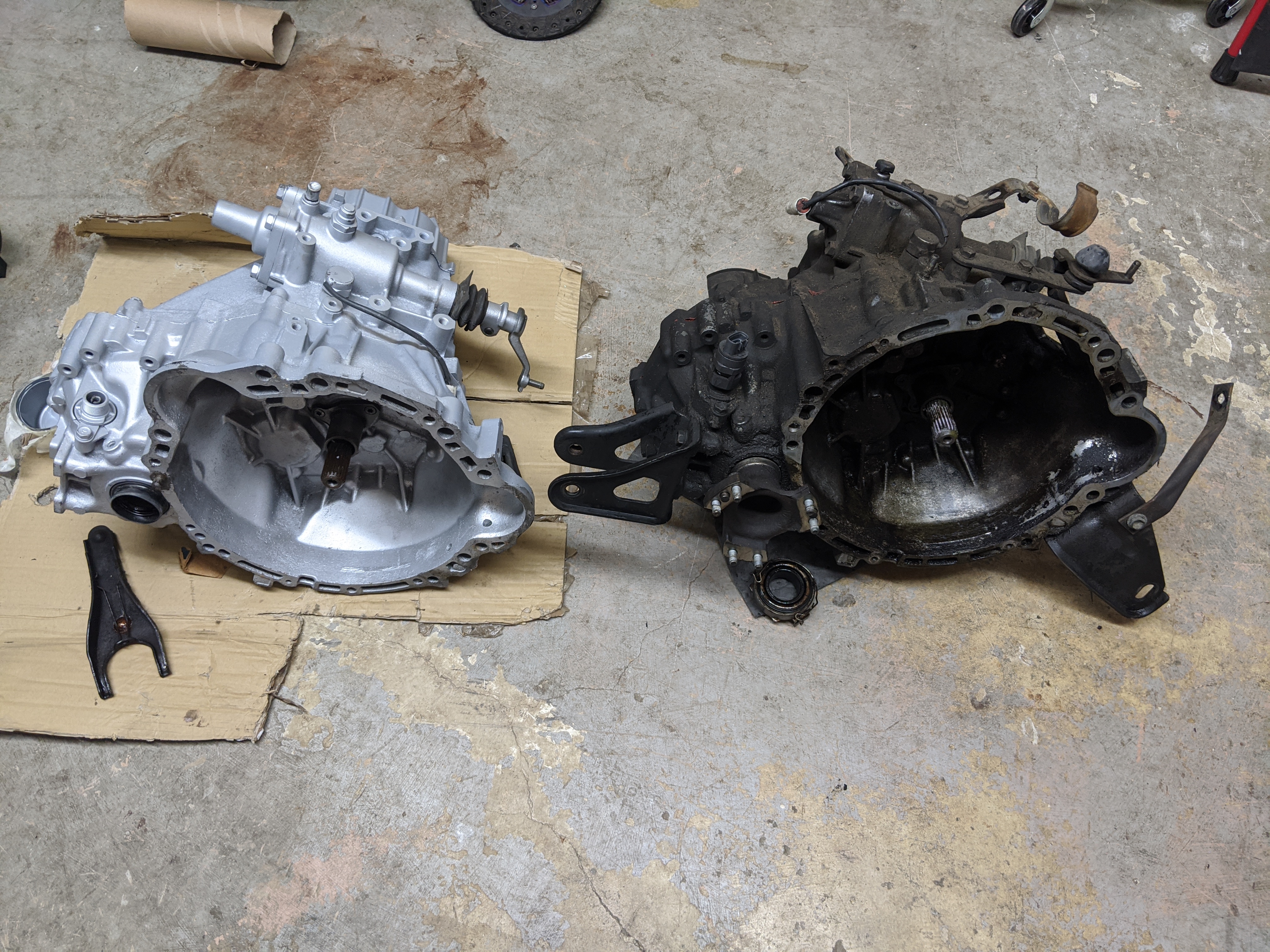
It's a car I wanted when I was young. It's cool; mid-engine, 2-seater, rear wheel drive. I put a 6 speed transmission in this one, to match the engine swap for a 1998 version of the original.
But this isn't a post about the transmission project, it's about the instrument cluster, and how I got here:
The setup
The year was 2017. I was having a good time enjoying my car, and the speedometer started to fail. I had replaced the ECU (engine control unit) with a programmable option, so I figured how hard could it be to build a new one from scratch, using CAN-bus instead of the twisty cable?
You might well guess that would be hard. You would be correct!
How the project started
I did some looking and originally settled on a Particle Photon microcontroller. I had wanted to do some interconnectivity stuff eventually and Particle had a cellular option if I got there. Their docs were pretty friendly too.
The software
There was little to do but start from scratch. I modeled my car's state in a C++ struct and built a loop that would read messages from CAN and build up the state. I had this running before I built the display component, which I just bound to the state structure.
The CAN message structure I defined had to be 2 messages. There was too much to stuff into 1 frame. I split things I wanted to be updated very frequently, like tachometer, from things that don't change very quickly, like fuel level.
The display
For the display, I started with a 4d Systems gen4-uLCD-70D-SB. I did this because I wanted to use a graphics IDE and have another company handle the graphics, to keep the project from ballooning out of control.
Hooray, right? I mean it's kind of ugly, but I got a test running quickly. But the devil is in the details... Why is the tachometer so small? Well because... (Yes I know this is a speedometer, but that's how it was styled by 4d Systems, and I was checking it for performance before re-skinning it as a tach)
The 4d Systems IDE outputs an image for each permutation of each instrument. So if you overlap instruments, the permutations get out of control.
Also, the fill rate on this 800x600 display was something like 1.4 million pixels per second. Sounds like a lot, but if you have a gauge cluster that overlaps and touches the whole panel, or most of it, you dip below 3 frames per second, because math.
This basic looking cluster had terrible performance. The tachometer moved choppily. You can clearly see the tearing in the video, but it was much worse in real life. Come on, I'm driving a 1987 Toyota here, it should be a luxury, prime experience right? :-p
A whole new sort of project
So... I decided to take matters into my own hands. Things got intense.
Display drivers, and legal trouble
I wrote a library for the serial controller on the 4d systems display. I thought I would use the low level shapes and whatnot to assemble a cluster from some primitives. It turns out my employer at the time, Amazon, was extremely hyper- sensitive about anything they could possibly consider to be adjacent to video games.
I got pulled into a tiff with some lawyers. I had to send them PDF's of the display's documentation to show them that I was just making a bindings library. That was a pretty annoying way to spend a bunch of time, but at least they accepted that "a translation from a public pdf about a device to a programming language does not constitute a breach of a video game noncompete employment clause." Thanks amazon. Anyway...
I tried to make the Diablo16 work with this, I really did. I found out that it supported transparency! So I made a couple assets, re-learned a bunch of math, and plotted a tachometer moving about an axis. It looked pretty, but it performed worse than the 4d Systems IDE approach.
Photoshop, Python, Visual Basic (oh my)
I was in trouble at this point. My car was torn apart and I desperately wanted to drive it again. So I had to forge forward.
The Diablo16 was horrible at transparency. So bad, it was something like 1/5 the speed of drawing just a literal image. But the permutation-of-images approach is too limiting. The SD card and bandwidth requirements weren't realistic. I wanted 60fps smooth display, with an attractive design.
So off to Photoshop I went. I ripped off the Lexus LFA instrument cluster style, because of the relationship of Toyota and Lexus. Also because I think the LFA is dope, and I liked the instrument cluster.
I designed the instrument cluster, and I designed Photoshop "animations" for each of the instruments. That wasn't too terribly difficult. But how to use it...
Photoshop had some COM interface documentation for Visual Basic. I wouldn't write VB, so I used Python, which had some image manipulation things I needed. So I was reduced to translating VB documentation of COM interfaces to Python COM calls to puppet Photoshop. You can do a lot with that interface.
I wrote a JSON description format to describe each instrument. It described the series of images for each instrument, including the gauge value for each position, the animation position for that value, the layer name for each gauge, and the x/y square for each gauge.
In this way, I only needed to make sure that none of the pixels overlapped in order to use the faster raw image write affordance in the Diablo16. At least, this was the theory I was operating under.
So the Python script would walk for each instrument, for each position, and export a png for the animation position, with a layer clipped at the indicated position. At the end, it outputted a C++ file with all of the descriptions statically hardcoded in such a way that I could re-generate the file and not have to re-write a bunch of display code.
Here's what photoshop looks like when puppeted by Python via the COM interface. It's basically a super-powered Action...
Optimization, and the secrets of old
I realized while doing this that I could conceivably use the alpha channel draw path, even though it was slow, because of the much smaller areas it was drawing. But the tachometer needle in the corners wasn't perfectly smooth. It's still a pretty big square.
When I saw this running on the display, I started to feel that sense of "holy shit, this might work." You can see there's garbage left over from the previous needle position at each new draw. That led me to re-invent a video game trick from long ago, the notion of "dirty rectangles." I later learned that name, but I was pretty proud of myself for realizing that I could exploit this in a couple ways.
Firstly, I needed to track the previous position so I could re-draw anything underneath it when it moved. Secondly, I changed my Python script and JSON description from a cutout per gauge position to a list of cutouts per gauge position. This was pretty labor intensive. I made several small squares when the tachometer was near a 45 degree angle, and I made just 1 when it was nearly horizontal or vertical. A re-export from Photoshop, some updates to the drawing strategy to use a list, and...
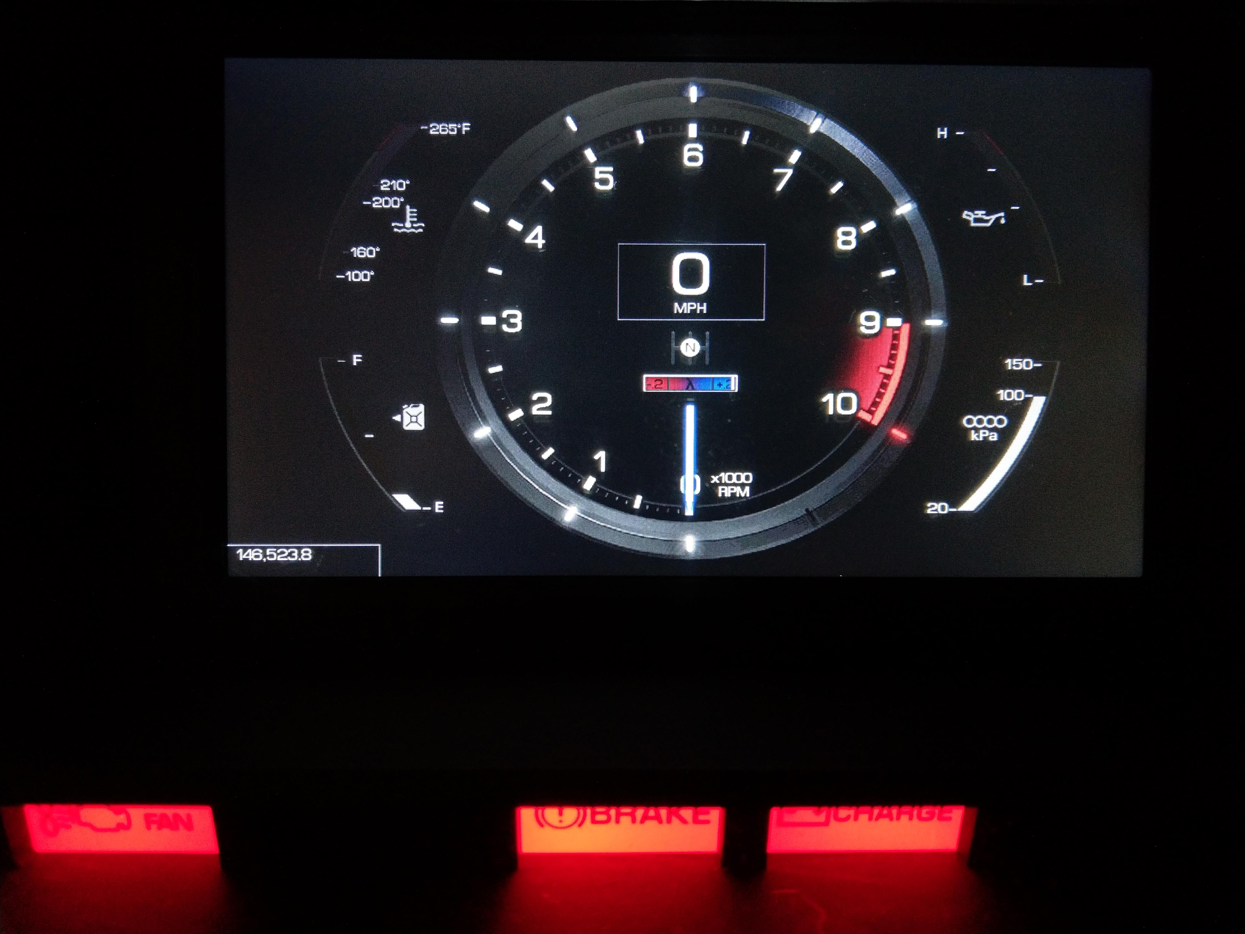
Finally, an optimized display that could draw what I wanted it to at 60fps. Sure, the panel has poor refresh rate, but logically it's working pretty well. No compromises with a gauge making another gauge update slowly due to jpg sizes. No worry about fill rate because the actual moving pixels are relatively few, and the fill is minimized. This is a worst-case test and it looks smooth in person.
Installation, and victory lap
Once this test was working, it did not take me long to decide it was time to install it and go. Here's a video of a final go/no-go test in the trunk of the car, with the data fed by the ECU over CAN instead of being fed by Python over USB.
WARNING: LOUD AUDIO
Hooray! I pulled the CAN wire to the front of the car, replaced the speedometer cable with a VSS sender, hooked it up to the ECU & programmed it, re-routed the gas tank wire to the ECU, and a whole host of other wiring updates.
The speedometer was fun to add. I tested it with the car lifted off the ground to see it work. Really, though, at this point, the project had become fun because I knew it was going to succeed. I had proven that the electrical feed would work, that the logical connection to the ECU would work, and that the display could show what I wanted it to, how I wanted it to show it - at least well enough!
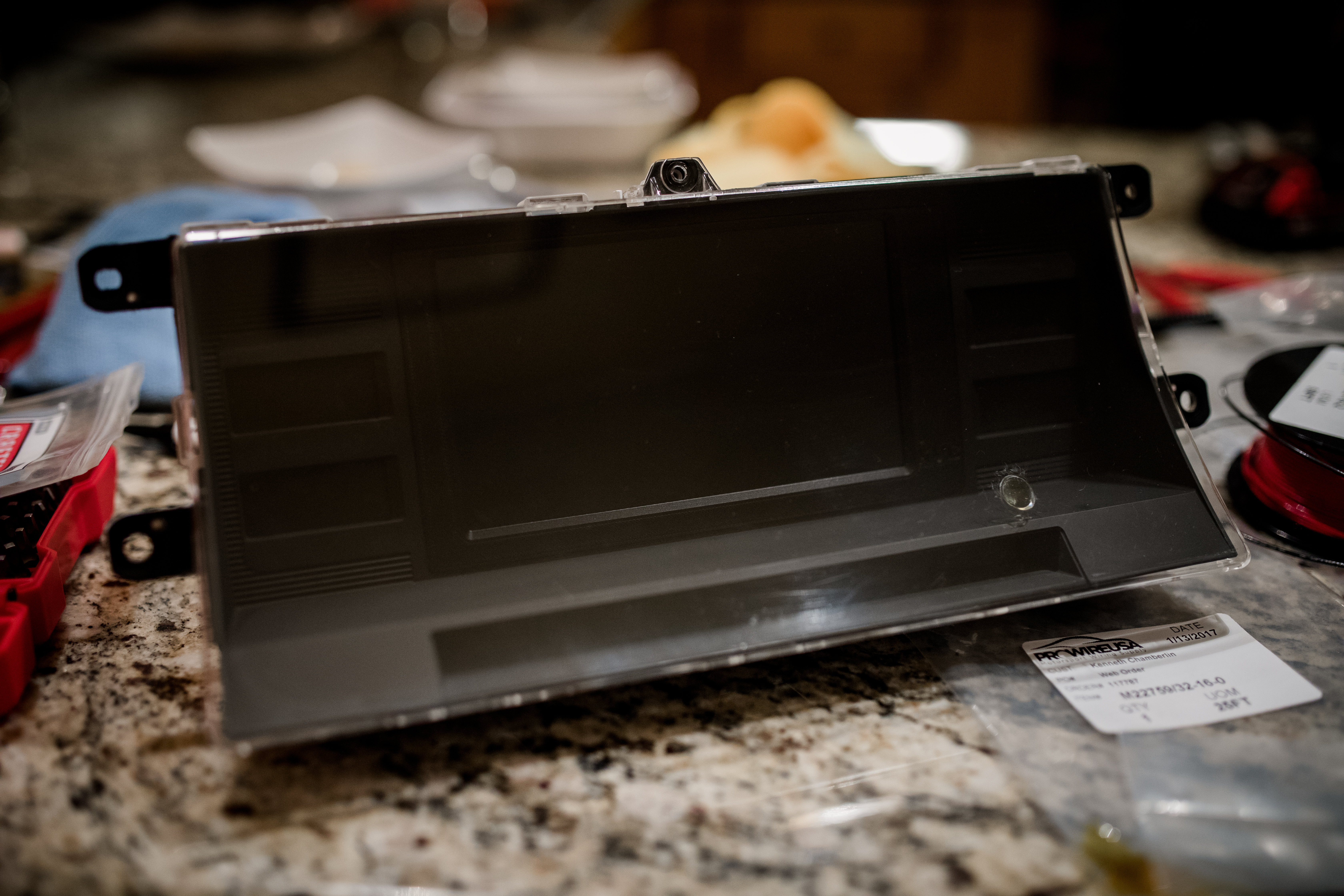 I spent a lot of time on this. I had selected this screen size so I could 3d print a bezel that would fit it right into the original cluster box. I filled the trip computer hole with some clear epoxy to keep dust accumulation low. It's less visible in reality than this picture suggests.
Done
Some cursing, a few bug fixes, and some gentle handling of 35 year old plastic later, and it was in the car.
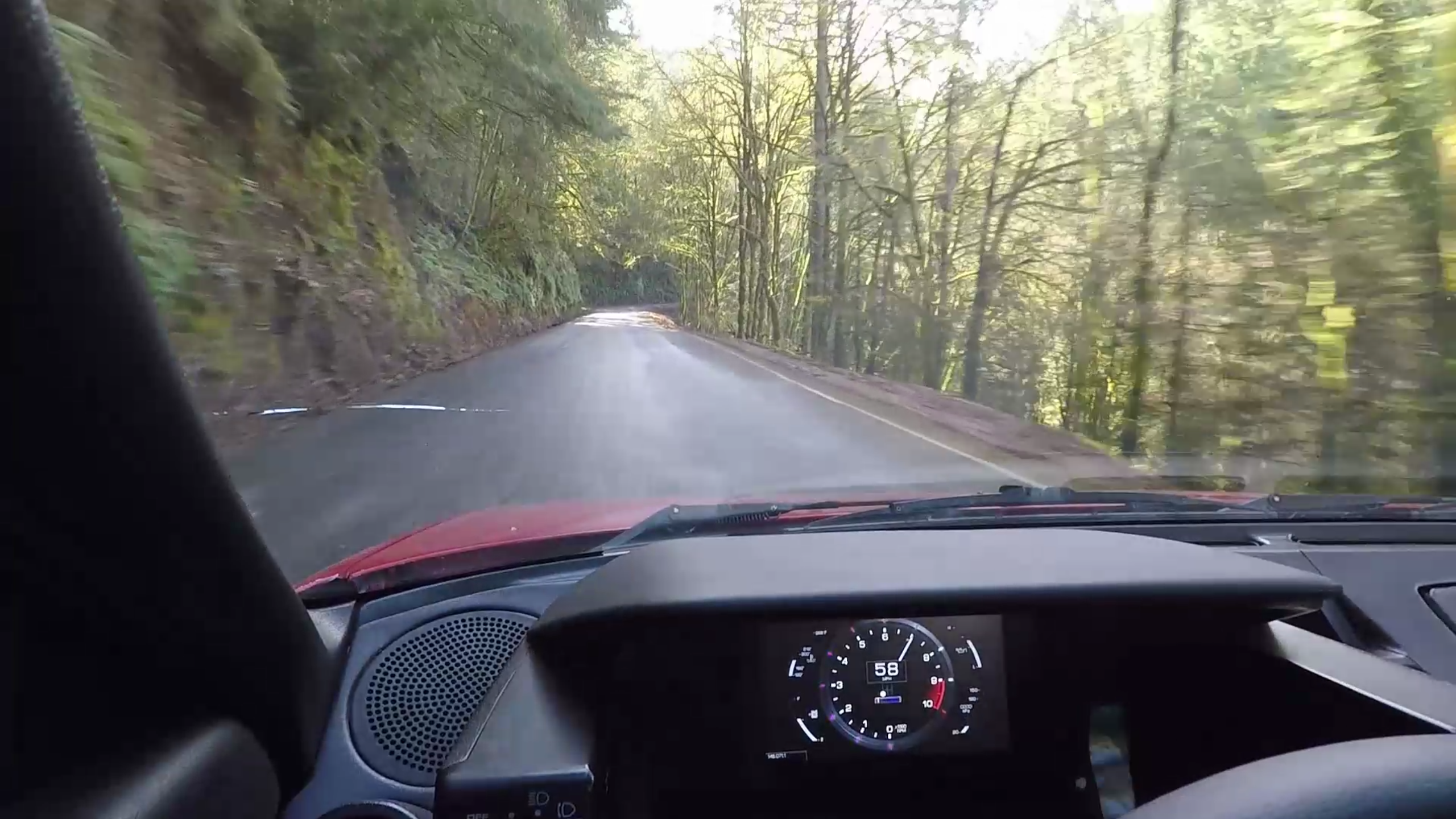
WARNING: LOUD AUDIO I did a drive to cycle the cluster through its different states. I made the pseudo-lights around the tachometer ring light blue when VVT is engaged, and red when the rev limiter is near. So I had to explore both of those things.
"Where is the code," you might ask! It's a tragedy, but all of the project code for this instrument cluster is lost. I have no idea where it is. As I was finishing up this project I got some other screens without a serial interface, EVE2 displays from Newhaven. These displays are so awesome after working with the 4d Systems displays. I have an old friend who hates EVE2, but I suspect that's because he's a professional.
I reimplemented the instrument cluster with EVE2, and I didn't need to do any optimization. It just plops images with alpha channels on the display as if it were nothing. It's so nice. But I never really cared to pull my car apart and replace the old cluster. So I've been doing some hacking to try and make a reason to switch, like a cluster that looks like it might belong in an 80's car...
WARNING: LOUD AUDIO I like this instrument that displays tachometer, MAP, and can handle VVT all in one. I got the idea from another old 80's car with a sweet digi-dash. But I think I need more features than this to really motivate me to pull the car apart again. Maybe a navigation interop...